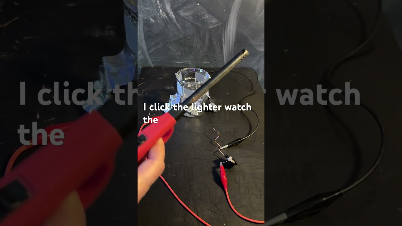
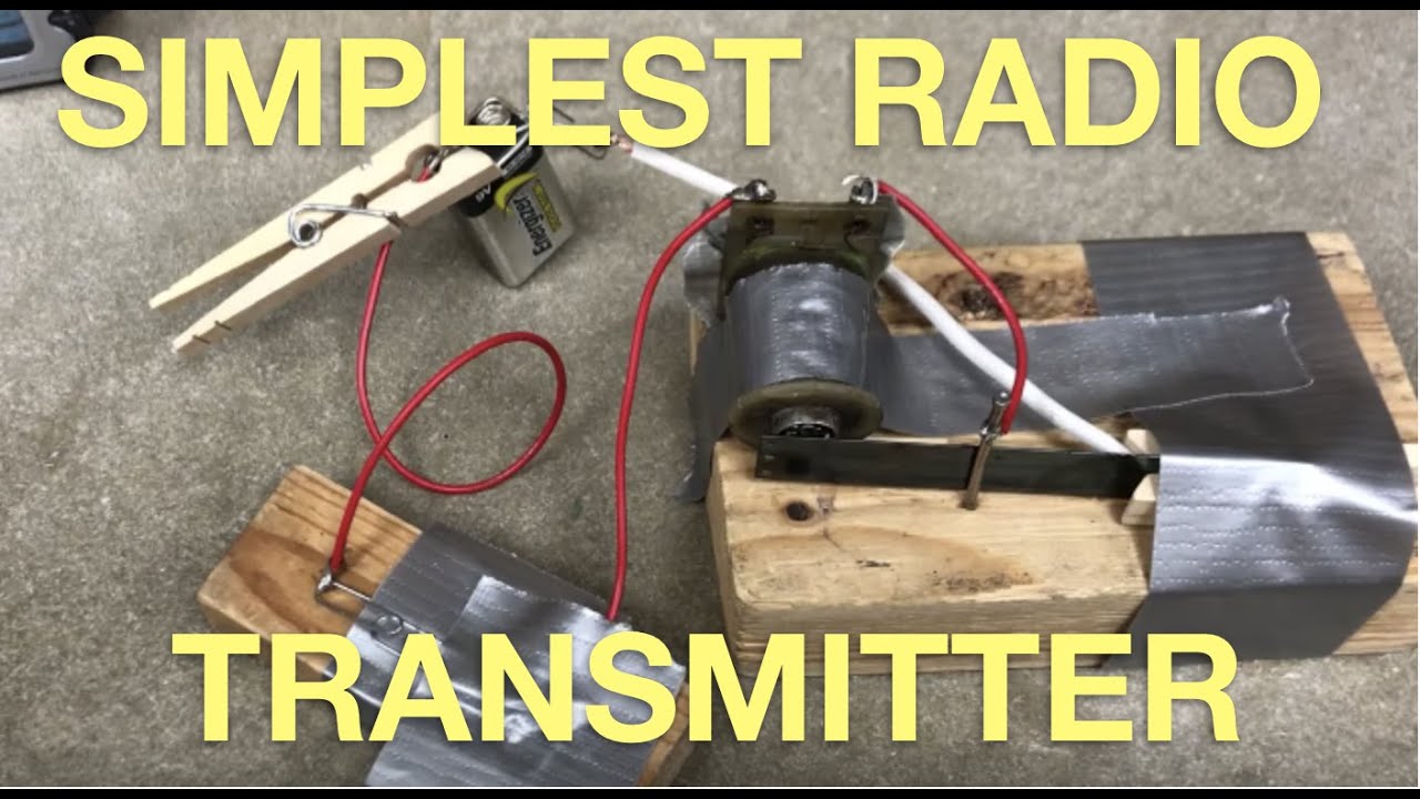
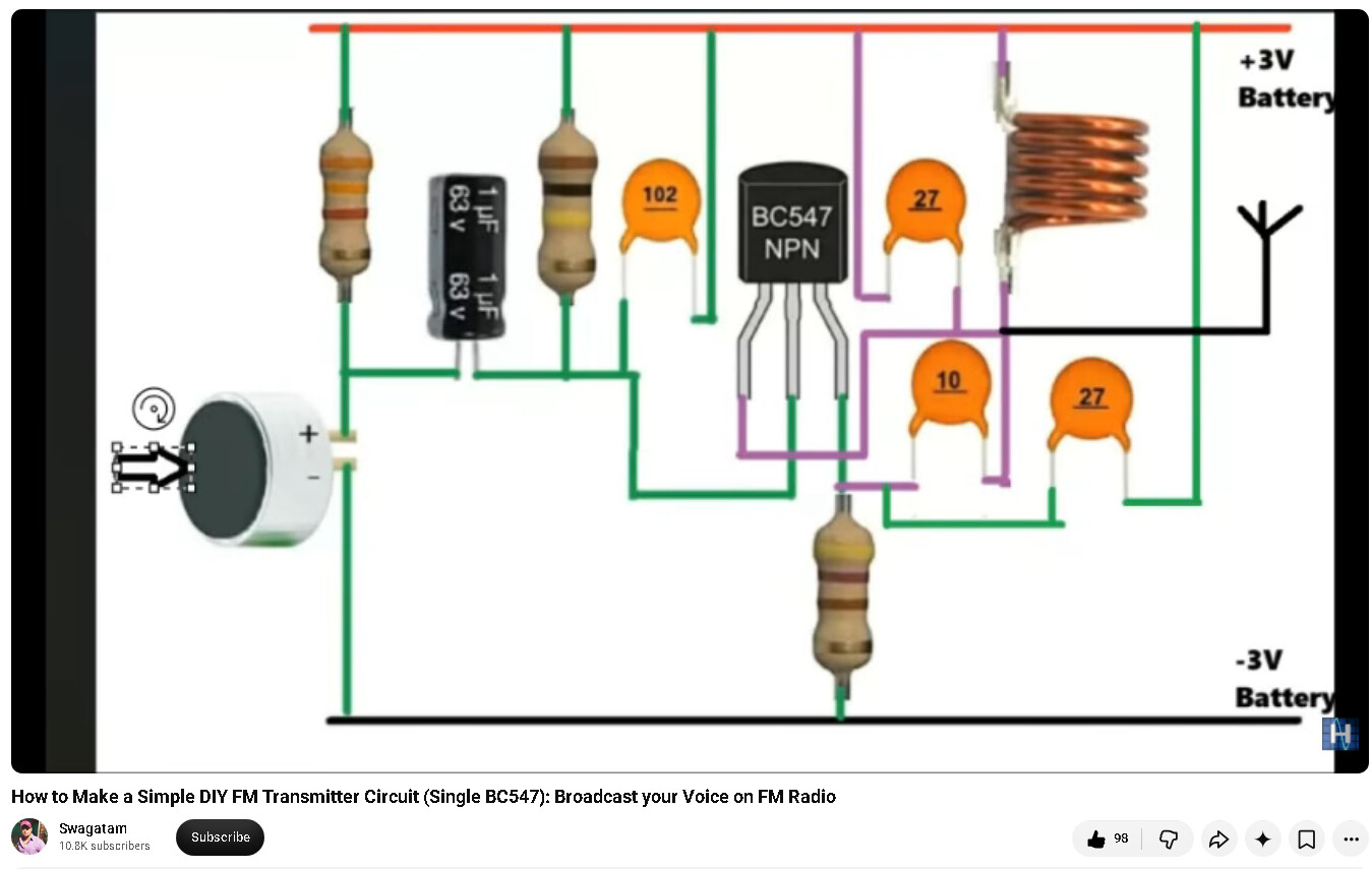
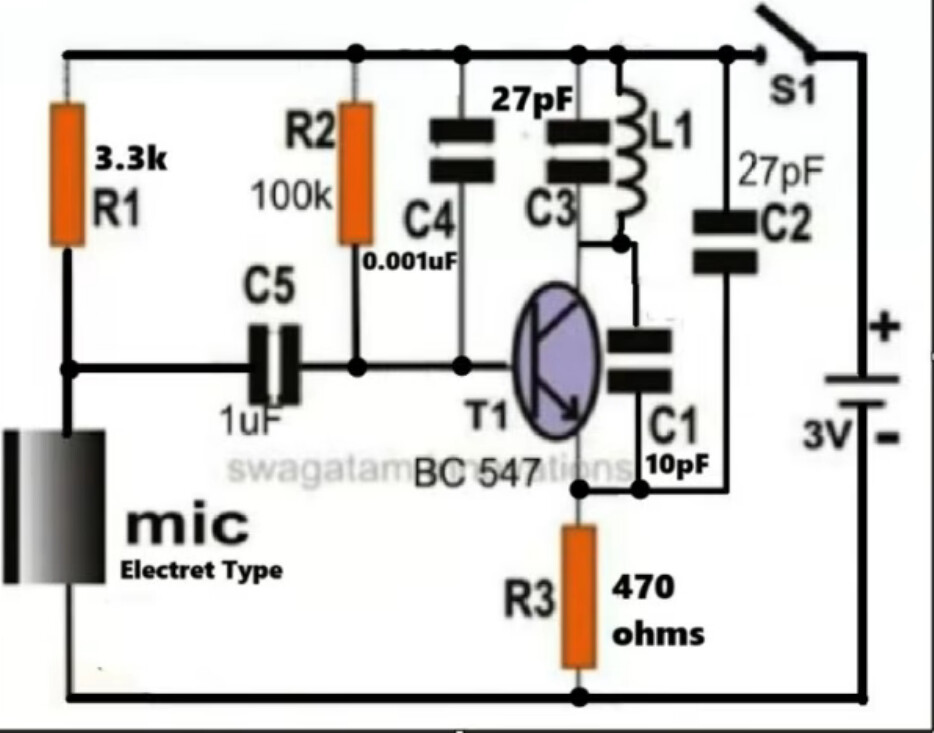
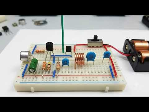
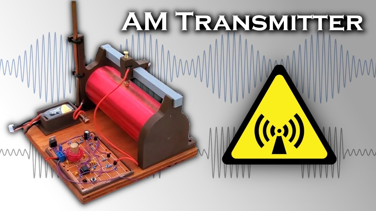
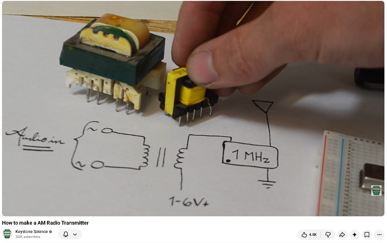
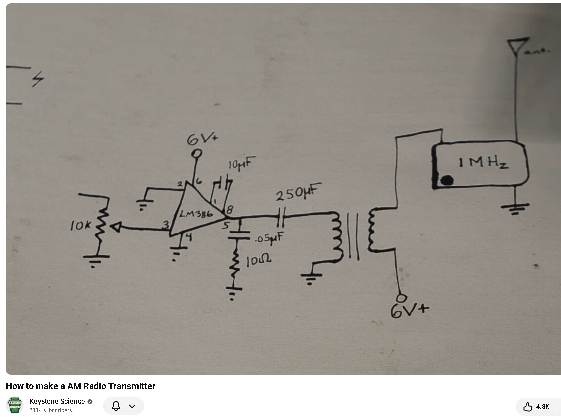
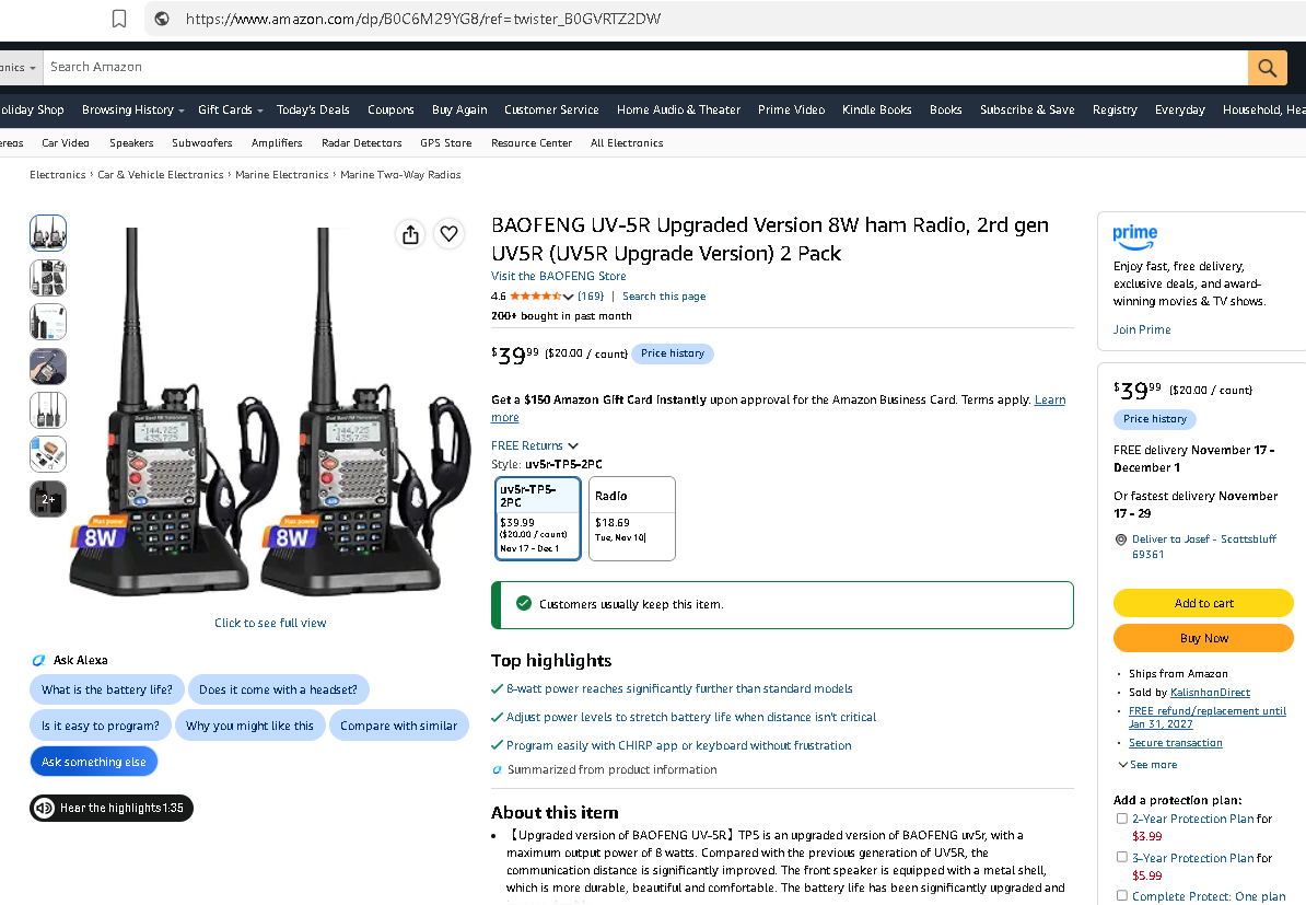
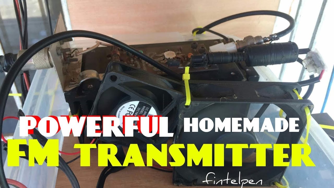
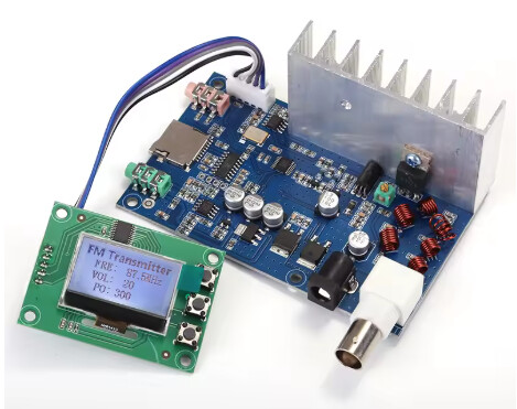
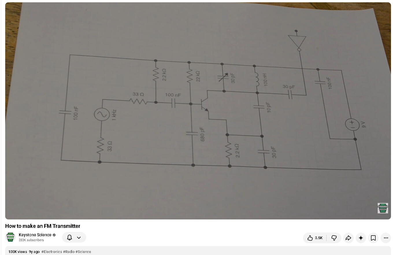
Looks like he’s going live tonight with a very fun and very cool project to get a 100W antennae going. This was done a year ago by the second video, but always nice to see a second take on this ancient technology making a comeback just in time for distributed internet (p2p) radio communications!
Coming up to bat - Ground-to-ground (NO LICENSE!) communications, a healthier alternative for the family jewels, extended range, reliable (weather don’t matter) p2p internet! Stay tuned!
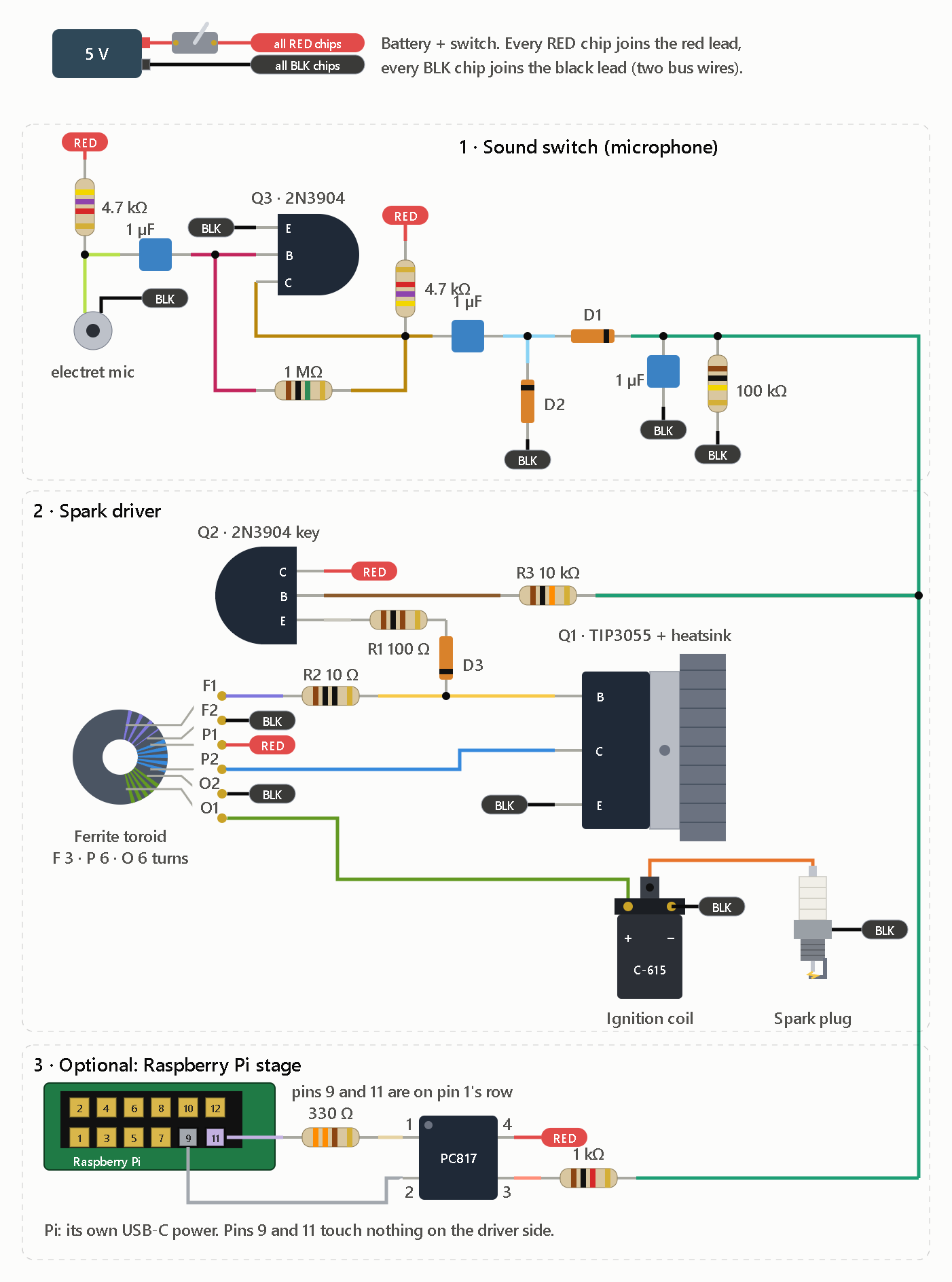
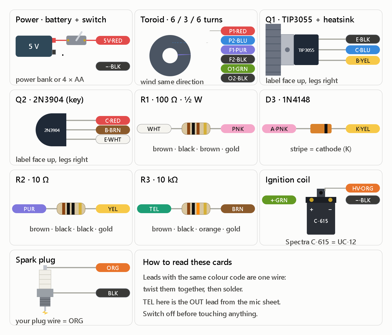
Top: the battery and switch. Every RED chip anywhere in the drawing is soldered to the red lead, and every BLK chip to the black lead. Two bus wires, or a pair of terminal strips, make that easy.
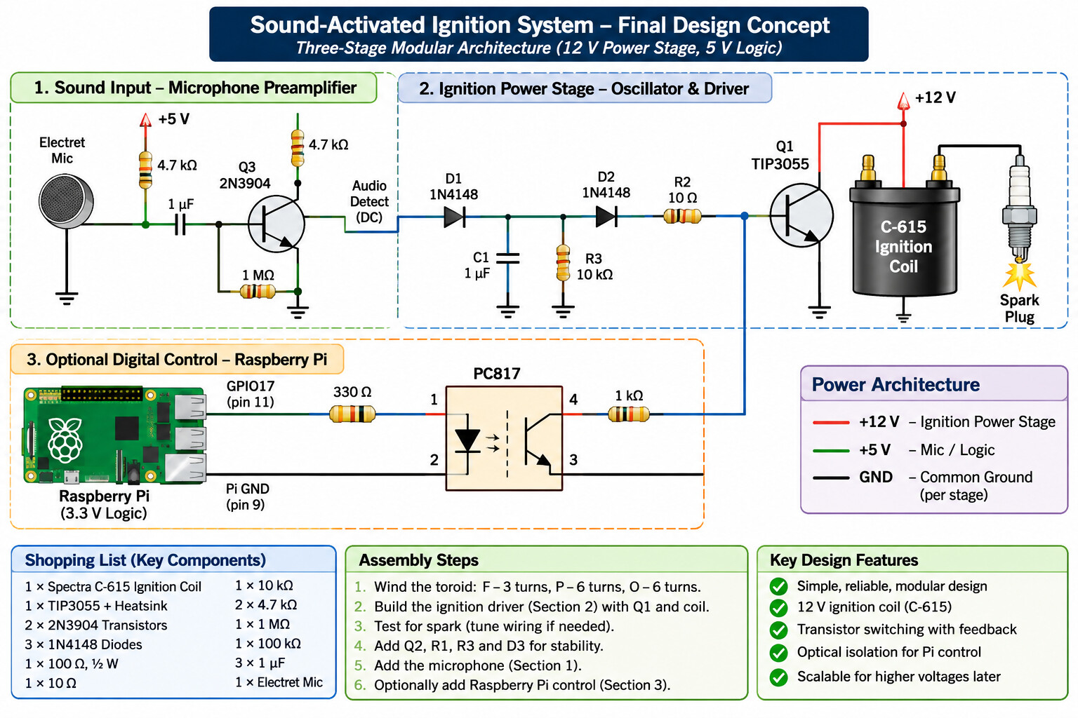
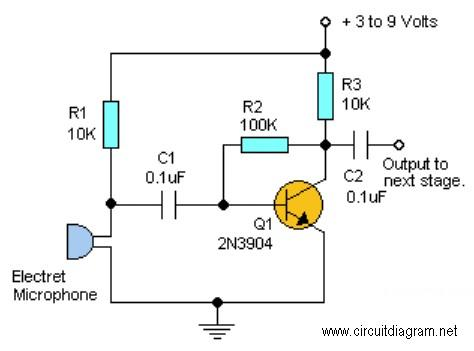
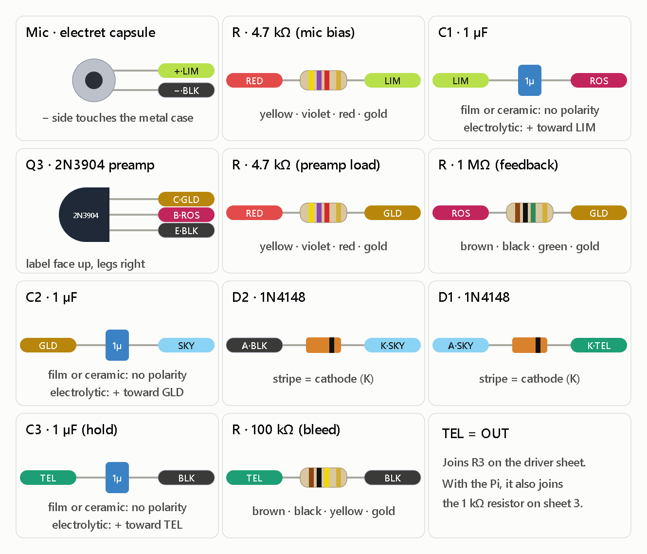
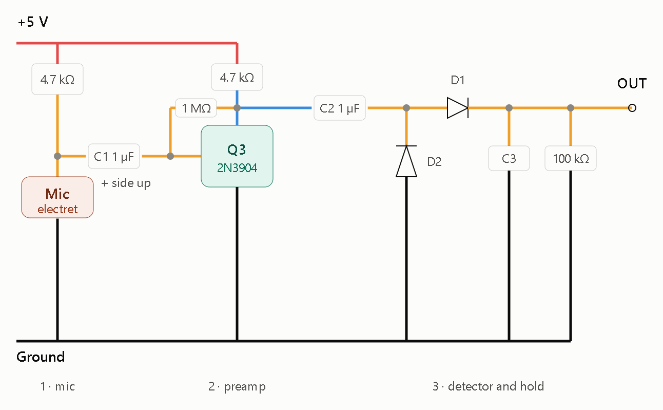
Section 1, sound switch: the mic, the Q3 preamp, and the diode detector. Its output is the teal OUT wire, which runs down the right edge.
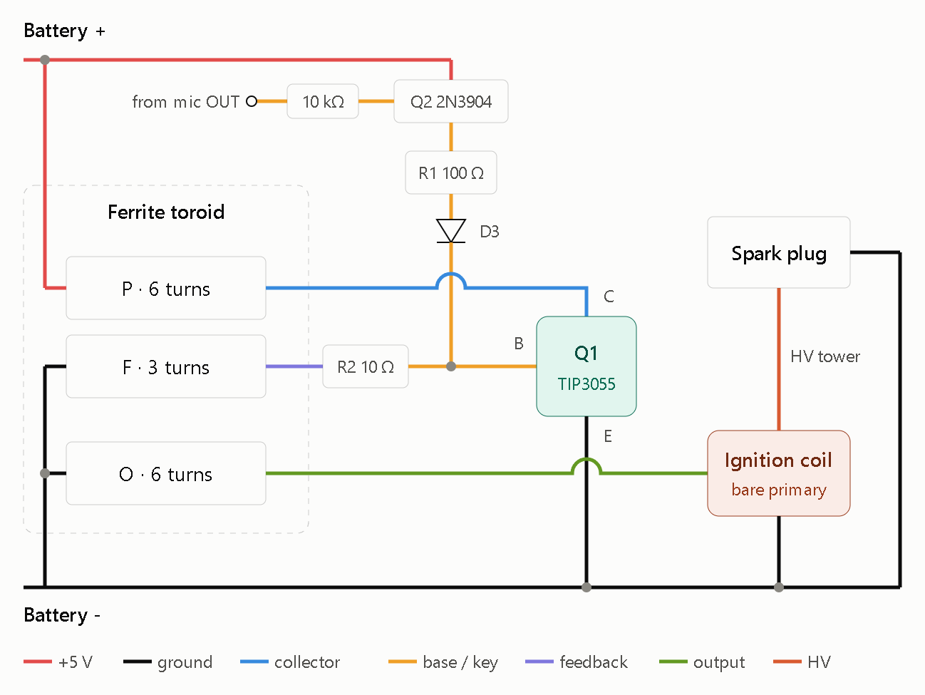
Section 2, spark driver: the toroid, Q1 on its heatsink, the coil and the plug. Q2 is the key transistor. OUT passes through R3 to Q2’s base, so sound switches the spark.
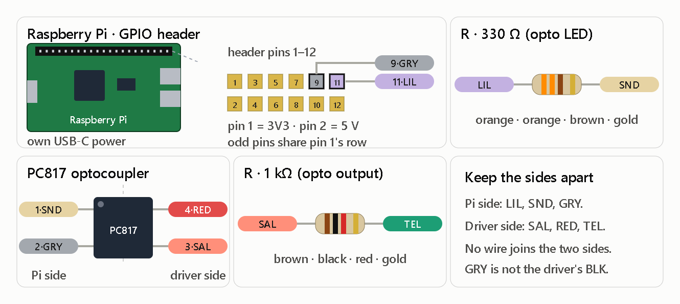
Section 3 (dashed, optional): the Pi stage. The PC817 pulls the same OUT wire high through the 1 kΩ resistor. Without the Pi, leave this whole section out and nothing else changes.
Build order
Build section 2 alone first. Jumper RED to the wire joining R1 and Q2’s E leg, so the key transistor is bypassed. Power it for 1 to 2 seconds. If you get no spark, swap the two F leads on the toroid.
Remove the jumper and add section 1. A clap should start the spark.
Add section 3 last, if you want it.
Things I haven’t verified
Resistor and capacitor values: all are starting points that I haven’t bench-tested.
Coil: measure the C-615’s primary resistance when it arrives. If it reads under about 1 Ω, use a strong supply.
Toroid: it has to be ferrite. The inverter core won’t work here.
Pi pins: the top and bottom rows of the header are drawn arbitrarily. Go by the pin numbers, not by which row looks higher. Pin 1 is the 3V3 pin, pin 2 (5 V) sits directly across from it, and pins 9 and 11 are on pin 1’s row.
Wire colors: the white wire from Q2’s E leg to R1 is drawn light gray so it shows up on a light background. It’s still the WHT wire.
Keep your hands off the plug and HV lead while it’s powered.
Without the Pi, build sheets 1 and 2. With the Pi, build all three. Sheet 3 only adds parts and doesn’t change anything on the other two.
Build order
Wind the toroid and build sheet 1 alone. Use a ferrite toroid (6, 3 and 6 turns), not the inverter core.
For the first test, temporarily jumper a wire from RED to R1’s WHT lead. That bypasses Q2. Power it for 1 to 2 seconds, and you should hear a buzz and see a spark. If nothing happens, swap the F1 and F2 leads.
Remove the jumper and build sheet 2. A clap should start the spark, and silence should stop it.
Add sheet 3 only when you’re ready for the Pi. The Pi gets its own USB-C power, and none of its leads touch the driver’s BLK or RED except through the PC817.
Checks
Heatsink: put an insulating pad between the TIP3055 tab and the heatsink, since the tab is the collector.
Coil: measure the C-615’s primary resistance when it arrives, as noted above.
Pi pins: pin 1 is the 3V3 pin, and pin 2 (5 V) sits directly across from it. Pins 9 and 11 are on pin 1’s row. Pin 9 is ground and pin 11 is GPIO17, which you’ll set high to fire the spark.
Safety: keep your hands off the HV lead while it’s powered.
One electret mic, a ferrite toroid, hookup wire, and a switch in the +5 V line
Build order
Wind the toroid: P 6 turns, F 3 turns, O 6 turns, all in the same direction, with the leads tagged.
Test the driver alone: build only the first diagram. Temporarily jumper +5 V straight to R1’s top and leave Q2 out. Power it for 1 to 2 seconds. You should hear a buzz and see a spark across the plug gap. If you get nothing, swap the F leads.
Add the sound switch: remove the jumper, install Q2, D3 and the 10 kΩ resistor, then build the mic block. Connect its OUT terminal to the “from mic OUT” terminal on Q2. Now a clap or voice should start the spark, and silence should stop it.
Tune it:
Fires on its own: make the 100 kΩ bleed resistor smaller, move the mic away from the spark, and shorten the mic wires.
Needs shouting: make the 100 kΩ bleed resistor larger, or try a 2.2 kΩ resistor in place of the preamp’s 4.7 kΩ collector resistor.
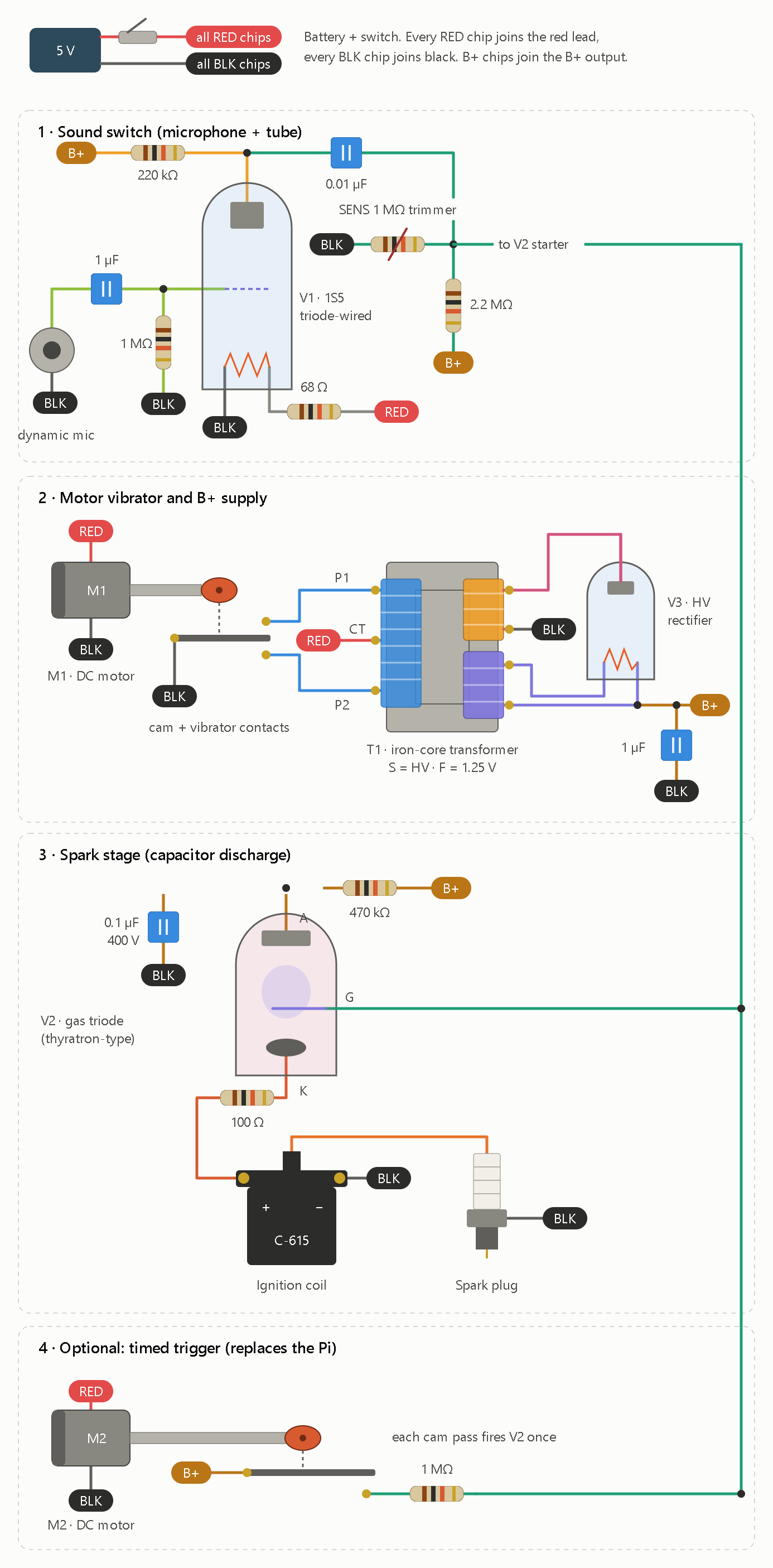
I drew it in the same chip-and-component style as your schematic, with the stages renumbered 1 to 4. It uses only DC motors and vacuum tubes, and no lamps.
The drawing shows these stages:
Sound switch: a dynamic mic feeds a 1S5 tube with its screen tied to the plate. Its output drives the starter of a gas triode (V2) through a SENS trimmer set just below the strike point. This is a threshold, so it responds to claps and sharp sounds, not sustained noise.
B+ supply: motor M1 turns a cam that rocks vibrator contacts across a center-tapped iron-core transformer. A tube rectifier (V3) turns that into about 150 to 300 V of B+.
Spark stage: B+ charges a 0.1 µF capacitor through 470 kΩ. When V2 fires, the capacitor dumps through 100 Ω into the C-615 coil and spark plug.
Timed trigger: M2 and a cam close a contact that pushes the starter over its threshold on a schedule, replacing the Pi and PC817.
A few things to know before you build it:
The toroid is gone. I told you earlier that the toroid could take an extra winding, and that was wrong. A cam only switches about 100 to 300 times a second, and a ferrite toroid needs kilohertz or it saturates. T1 is a laminated iron-core transformer instead, and a small mains or filament transformer run in reverse is the cheap way to get one.
All the tube values are starting points. I haven’t verified a datasheet for any of them.
V1: the 1S5, with the 68 Ω dropper from 5V to its 1.4 V filament.
V3: the HV rectifier, which needs the filament winding F on T1. Check its filament voltage and current.
V2: the gas triode. Check its starter strike voltage and peak current.
Limit the discharge current. A 0.1 µF capacitor at 200 V into the coil primary can peak above what a small gas tube allows. Start with a smaller capacitor, or raise the 100 Ω, until the tube is within its rating.
Add a condenser across the vibrator contacts. About 0.1 µF, as in an ignition system. I left it off the drawing to keep the wiring clear.
Power draw is higher. The motors and the rectifier filament add up, so use a proper 5V supply rather than a small battery.
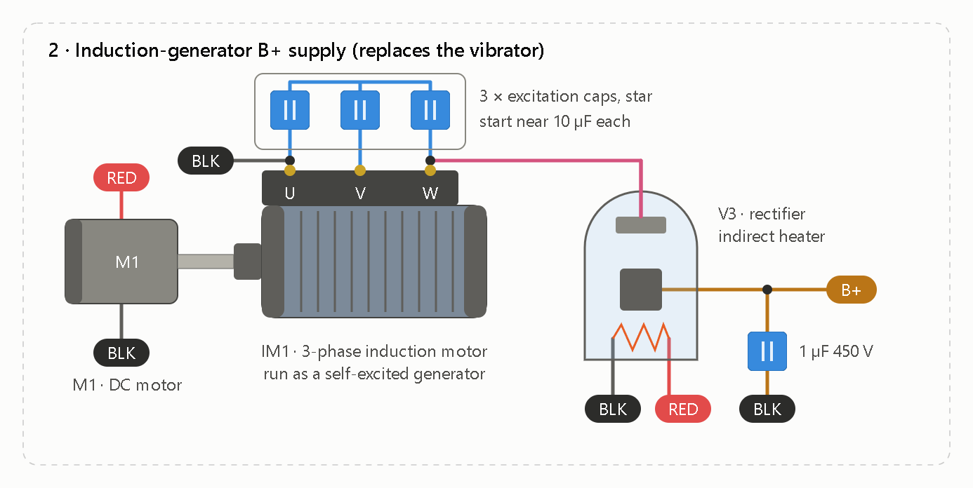
This replaces the whole vibrator in stage 2 (M1 plus the points, T1 and the old rectifier). Stages 1, 3 and 4 stay as drawn.
M1 spins the induction motor above its synchronous speed, with a small capacitor bank on its terminals. That makes it a self-excited induction generator. The rotor’s residual magnetism seeds the field, and the capacitors let the AC voltage build up. V3 then rectifies one winding (U to W) into B+. There are no contacts to burn, and the frequency comes from rotor speed, so the saturation problem I hit with the ferrite toroid goes away.
Size sets the power draw. A no-load induction generator still has to supply its own core and friction losses, and those grow with motor size. The spark stage draws almost no energy, so use the smallest 3-phase induction motor you can find. A 1/4 hp unit could pull 60 to 100 W just spinning, which is 12 A or more from 5V.
Speed matters more than torque. M1 has to hold the rotor above the motor’s synchronous speed (for a 4-pole motor on 60 Hz, 1800 rpm). A 5V DC motor needs a gear step-up to do that.
The capacitor value is a starting guess. Too little and the voltage never builds, and too much and it overshoots toward the winding’s insulation limit. Expect to tune it with a meter. Touching the motor leads briefly with a battery before the first spin can help leave the residual magnetism the field needs to start.
Output voltage follows the nameplate. A 230 V motor can give a few hundred volts peak, so I rated the filter cap at 450 V. Stage 3’s 0.1 µF capacitor then stores more energy, which makes the gas triode’s peak-current limit tighter.
V3’s heater needs care. The heater is fed from the 5V rail while the cathode sits at B+. Pick an indirectly heated rectifier with a heater-to-cathode rating well above your B+. A 6.3 V type will run slightly underheated at 5V, which is fine at this tiny current.
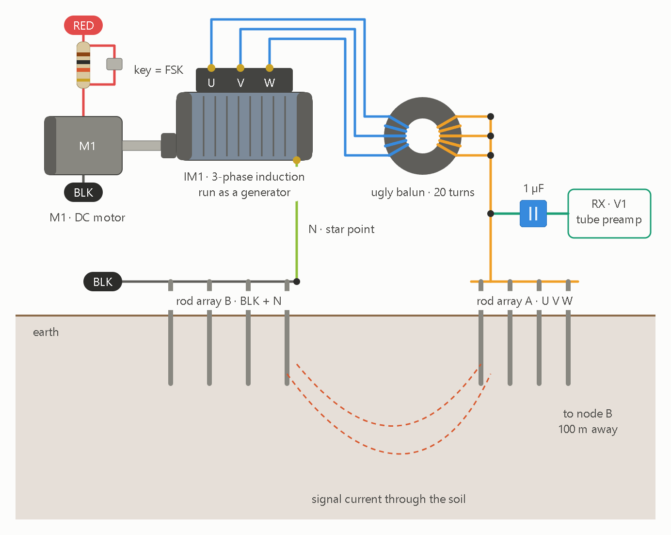
Here is how the drawing works, followed by the points that matter for building it.
Signal path. M1’s supply runs through a speed network with a key. The key shorts out part of that resistance, which shifts the speed and therefore IM1’s frequency, so keying gives FSK. U, V and W go through the 20-turn balun and are tied to rod array A. The star point N goes to rod array B, which is also the black lead. Current runs through the soil between the two arrays. The stage-1 tube preamp stays connected across the same rods at high impedance, so it listens while the node transmits. The node on the other end is a mirror image.
Because the balun forces U, V and W to carry equal current, the output is the zero-sequence part of the three phases, and that is what carries the signal. Cancellation by itself doesn’t raise efficiency. What couples into the soil is the small residual, so the design should create that residual on purpose.
Resonance is a tuning job in the hardware. The balun’s inductance, the electrode and soil resistance, and a series capacitor form a resonant loop at f = 1/(2π√LC). For example, a 10 mH balun needs about 1 mF to resonate at 50 Hz. Paralleled motor-run capacitors are the natural analog part for that. Your identity N = Ω·C²/(m·s) is dimensionally correct for the ohm, but it’s a units identity and doesn’t produce resonance on its own. The script’s Ω (m²/s⁷) is also a different quantity from the ohm. Separately, emergentC1.py multiplies the constants by an assumed 1.05, so its 5% change is an input, not a result.
hdgl_tte_protocol.ino is the digital version of this link. An AD9833 DDS does FSK at ±0.1 Hz around 3.915 Hz with Hamming-coded 4-bit frames. The receive side is a stub, and its comments say “Simulate reception”.
That raises a design issue for the motor version. At a 50 Hz carrier, ±0.1 Hz is about 0.2% of speed, roughly 3 rpm on a 4-pole machine. A 5V DC motor behind a series resistor won’t hold that, so M1 needs tach feedback or a mechanical governor. A 3.9 Hz carrier is worse. An induction generator at that frequency barely self-excites, because voltage scales with frequency and the excitation capacitance grows as 1/f².
Should the carrier be the motor’s own ~50 Hz, with the Schumann sub-harmonics as the modulation as in our waterfall sim, or the 3.9 Hz range from the Arduino?
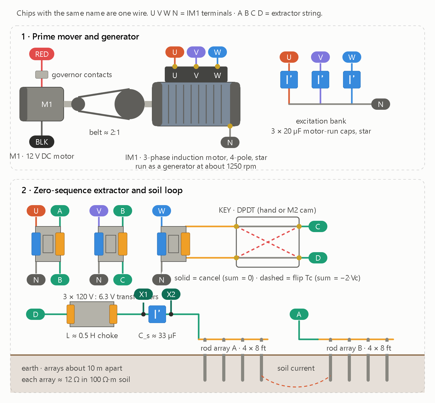
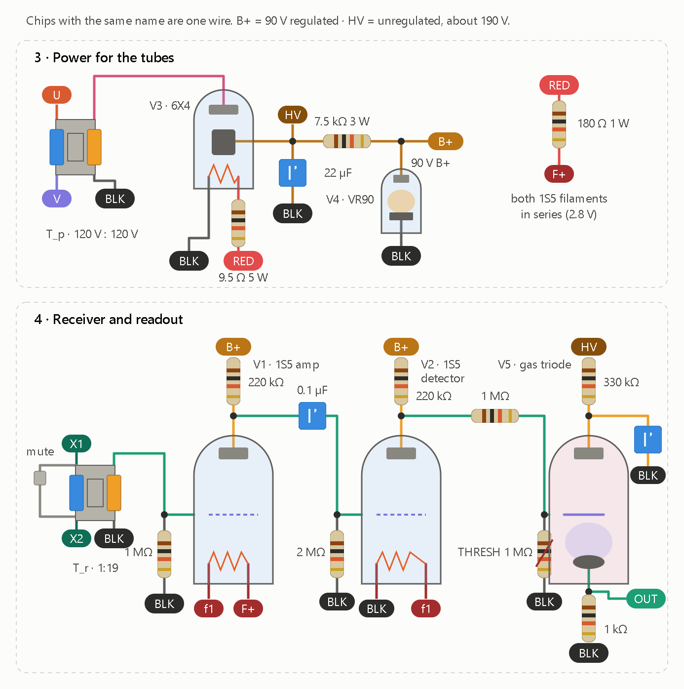
The numbers below are hand arithmetic, not a simulation, and every part value is a starting point to tune on the bench.
Item
Value
Why
Carrier
about 40 Hz
It sits 20 Hz from 60 Hz mains, so the loop’s Q rejects hum by roughly 14 dB.
IM1 speed
about 1250 rpm
A 4-pole machine generates slightly below its shaft frequency.
Excitation
3 × 20 µF star
C = I_m/(ωV) with I_m ≈ 0.4 A at 89 V per phase.
Extractor
120 V : 6.3 V ×3
Balanced gives 0 V. Key flipped gives about 9.4 V (−2 × 4.7 V).
Soil loop
L ≈ 0.5 H, C_s ≈ 33 µF
Resonates at 39 Hz. With about 34 Ω total it carries about 0.28 A (about 2.7 W) at Q ≈ 4.
Rod arrays
4 × 8 ft each, about 10 m apart
About 12 Ω per array in 100 Ω·m soil.
B+
T_p, 6X4, 22 µF, 7.5 kΩ, VR90
About 190 V unregulated, 90 V regulated. The 1S5 plate limit is 90 V.
Receive gain
Q × T_r (1:19) × V1 (about 12)
About 0.9 mV of field at 100 m becomes about 0.7 V at V2’s grid.
M1 needs a 12 V supply rather than 5V. Spinning the generator costs roughly 25 to 40 W, which is 8 A or more at 5V.
First light
Generator: run M1 and IM1 with no extractor connected. Touch a 12 V battery across two stator leads for a second to leave the residual magnetism, then check that the phase voltage builds to about 89 V at 40 Hz. Adjust the capacitance until it does.
Null: with the key idle, measure across the extractor string. It should read near 0 V. Flip the key and expect about 9 V.
Loop: connect the rods and trim C_s for peak loop current.
Receive: test across X1/X2 before connecting a second node. Adjust THRESH until V5 just stays dark, then key the far node.
Weak points
Signal margin: soil resistivity can swing the received level 10× either way, and I have 60 Hz noise estimated, not measured. If the margin is thin, wire V1 as a true pentode with a screen network for about 20 dB more gain.
Governor: it needs to hold within ±2% (±0.8 Hz). The loop passes about ±5 Hz, so that is fine.
Data rate: expect about 1 baud.
V5: I haven’t checked the strike and starter voltages for a 0A4G-type tube against the datasheet, so verify them before you build.
Safety: the node carries 154 V AC and 190 V DC, so enclose everything. The extractor transformers keep the generator isolated from the soil loop, so don’t bond the generator to the rods.
I dropped the spark and ignition-coil stage for this node. The second-node cooperation (each end modulating the other) would be the next step: V5’s output closes a keyer contact so a node can repeat what it hears.
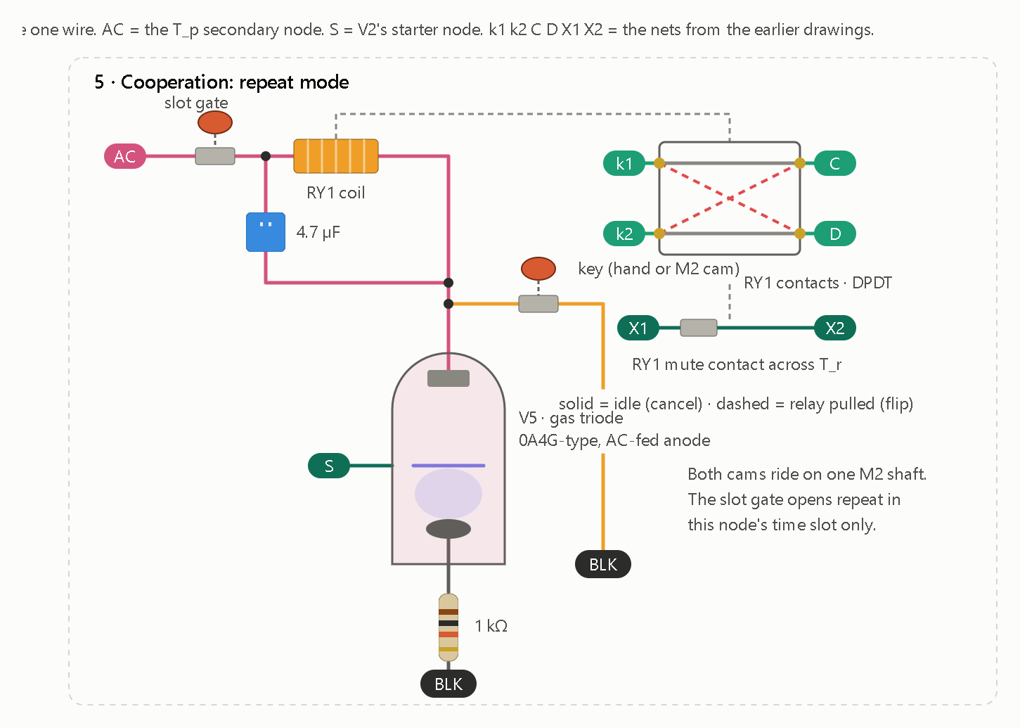
This stage lets a node repeat what it hears. V5 is wired as a relay tube, so its starter fires when a signal is detected, and the current through the relay coil pulls the relay. The same relay’s contacts flip the extractor key and mute the receiver, so the node transmits what it just received.
This stage replaces V5’s 330 kΩ anode feed and 0.047 µF capacitor from the second drawing.
How it works. The V5 anode runs off the generator’s AC through the relay coil, so the tube shuts off every cycle and can’t latch. Conduction follows the starter, so V5 conducts only while a signal is present. The 4.7 µF capacitor smooths the half-wave pulses so the plate relay holds. RY1’s DPDT contacts flip Tc in the extractor, which makes the node transmit. Its mute contact shorts T_r’s primary while RY1 is pulled, so the node doesn’t hear itself.
The two cams. M2’s cams give the node a time slot and a manual key.
Slot gate: the contact in series with the AC feed. It only lets the relay work during this node’s slot.
Key: a contact across V5 that forces the relay closed. Use it for a hand key or a notched message disc to send your own data.
What to watch
A relay is unavoidable here. Neither a tube nor a motor can switch the extractor’s secondary loop directly, so I used a plate relay, the classic partner of a gas tube. A 5 kΩ coil on this supply draws up to about 40 mA peak. I haven’t verified that the 0A4G-type tube you pick can carry that, so check its peak and average current ratings first. If it can’t, use a higher-impedance relay.
Ping-pong: two repeaters in range of each other can lock into hearing and re-sending the same message forever. The slot gate prevents it. Phase each node’s slot cam differently, and the mute contact covers the node’s own turn. In a chain, orient the rod dipoles so neighbors couple weakly.
Latency: it is detector τ (about 0.2 s) plus relay pull-in (about 20 to 50 ms), so a repeater adds about a quarter second per hop.
From prior, The Feedback Kill-Switch (RY1 Mute Contact)
A massive engineering problem with any signal repeater is local loop feedback (acoustic screeching in microphones, or latching in radio relays). If the node transmits a massive current into the dirt, its own ultra-sensitive receiver inputs (X1 and X2) will instantly detect it, keeping the node permanently jammed on.
The Solution: The circuit loops a dedicated auxiliary contact from RY1 across the primary input of the receiver’s step-up transformer ((T_{r})).
The instant the relay pulls to transmit, it hard-shorts nodes X1 and X2 together. The receiver is struck completely deaf for the exact duration of its own transmission pulse, guaranteeing it cannot hear itself or lock up.
Lets EMBRACE the feedback, and see what happens, minding the below as our physics.
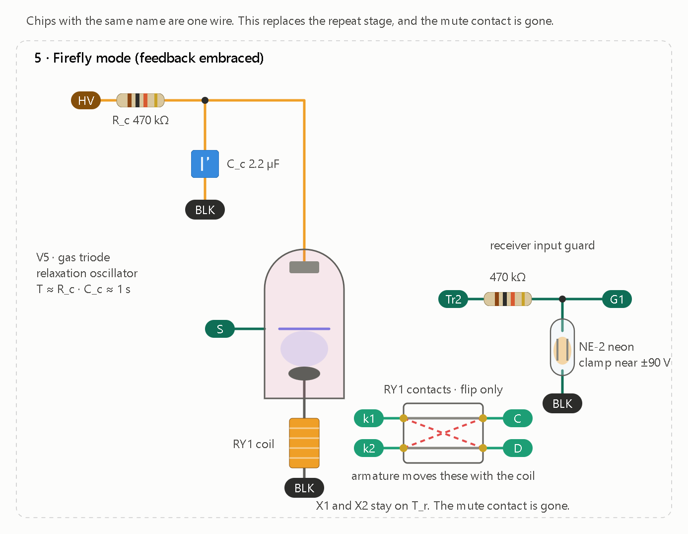
Removing the mute contact needs more than deleting a contact. When the node transmits, C_s carries about 47 V, and T_r at 1:19 would put roughly 900 V on V1’s grid. So the mute was also protecting the tube, not just preventing feedback. What the open loop does after that depends on the sign of the feedback:
Positive feedback (the current wiring): the node hears its own transmission, keeps V5 fired, and latches on. That is the failure the mute prevented.
Pulse feedback through a relaxation oscillator: the node pings, hears itself and its neighbors, and each ping nudges every node’s next ping. That is a pulse-coupled oscillator, the same math as fireflies synchronizing, and it is the closest real counterpart to your Kuramoto coupling.
I’d build the second one. V5 becomes the oscillator: HV charges C_c through R_c, the tube fires and discharges C_c through the relay coil, and the relay pings the soil. The detector output on the starter node is the coupling. A neighbor’s ping raises the starter bias, so it fires sooner.
Wiring: on T_r’s secondary, insert the guard between the Tr2 and G1 chips. Break the wire where it runs from T_r’s top lead to V1’s grid.
Components: in the second drawing, V5’s cathode now goes to the RY1 coil instead of the 1 kΩ resistor, and its anode is fed from HV through R_c with C_c to BLK.
Starting values are R_c = 470 kΩ and C_c = 2.2 µF. They are chosen so the node pings about once per second (T ≈ 0.98·R_c·C_c). If V5 won’t extinguish between pings, raise R_c. If the relay doesn’t pull, raise C_c. These assume a 190 V HV rail, a transfer voltage of about 130 V and extinction near 30 V. I haven’t checked the 0A4G-type datasheet for those, so verify them before building.
The self-feedback is harmless here. A node’s own ping raises its starter bias only after it has fired, while C_c is still recharging, so it can’t re-fire early. At most it shortens the period slightly.
What to test
One node alone: it should free-run at about 1 Hz. Compare its period with the guard output grounded (G1 to BLK) and with it connected. The difference is the node’s self-coupling.
Two nodes, ratio sweep: set T_B/T_A to 1.00, 1.50, 1.618 and 2.00 by changing C_c, and log ping times for 50 or more cycles. A lock means a constant phase difference between the pings. The hypotheses disagree about φ:
Standard pulse-coupled dynamics: locking at small-integer ratios (1:1, 3:2, 2:1) and none at φ, because the golden ratio is the hardest ratio to lock.
The attached document: φ-related frequencies resonate and amplify, so it predicts locking at 1.618.A clean no-lock at 1.618 argues against the document, and a lock at 1.618 would argue for it. Either result is informative, but only if the other detunings are logged alongside it.
Three or more nodes: expect near-synchrony from similar nodes. Relay pull-in plus the detector’s 0.2 s tail will keep it from being exact.
Log ping times by measuring across a spare rod pair or across the RY1 coil, so the measurement doesn’t load the loop.
Weak points
Neon clamp: the 470 kΩ limits the clamp current to about 1.7 mA, which is near the NE-2’s limit. If the bulb runs bright, go to 1 MΩ and accept 6 dB less sensitivity.
Detector tail: the 0.2 s detector decay is a fifth of T, so a neighbor’s ping is felt for a long stretch. That helps entrainment but blurs phase. If locks look sloppy, shorten the grid-leak time constant.